Physics - Friction 3
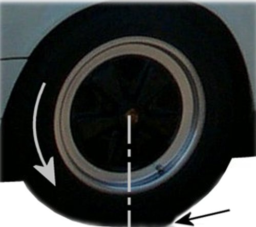
| Tire contact area offset to the rear when wheel is pushed |
Until now, the friction partners were more or less solid. At this chapter we assume much more deformable materials. The motor vehicle is full of them. No engineer would think of connecting the engine or even the entire
drive unit including the exhaust system to the chassis, perhaps in the case of a motorcycle, but there are also many deviations.
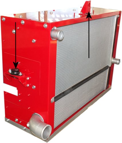
Even with large radiators, e.g. in trucks, which are connected to the engine via rubber moulded parts (picture above), you have to pay attention to possible vibrations and suspend them a bit more flexibly. Belt drives can
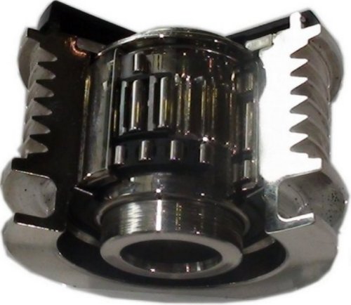
also be equipped with a freewheel (picture below) to protect them from vibrations in the drive despite the possible compensation by the belt itself, e.g. in the driven wheel of the generator.
In order to show what such connections have to do with the phenomenon of friction, a good initial example is the tyre on the road, simplified as a non-driven, but running wheel (picture at the top). We talk about tire caster
and mean that when the tire is spinning, the contact area is slightly behind the one when the tire is stationary. This causes deformations at the tire flank with itself, in addition to those caused by the weight of the vehicle and
the road shock dampers.
And deformations always have something to do with inner friction of the tire. If it rotates, these must be propagated once through the entire sidewall during one revolution. This then happens 500 times per km at a roughly
estimated wheel circumference of two meters. You can imagine that this deformation work also has some effect on the efficiency.
But the tyre caster also has a positive side, because it stabilises the wheel in a straight line. In general, it is a typical feature of elastic deformation, as opposed to plastic deformation, that it always tries to return to its
original state. However, this happens sometimes too fast with counter-reactions, so that e.g. with the landing gear one tries to dampen such vibrations.
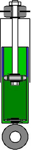
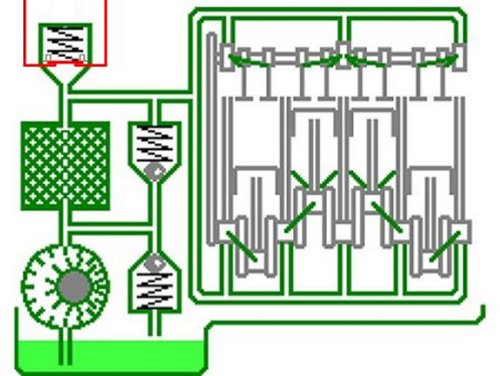
If then in a vibration damper a piston has to pass through a space filled with oil (picture above) and the oil passes valves in its interior, we are again dealing with friction, at least with liquid friction. Easy to understand: For
example, one could measure the temperature of the dampers after a particularly successful ride on a country road and be glad not to have touched them with the fingers.
There we have it again, the (heat-) losses through friction. How do they actually come about? In the end, the losses we register on the car are usually caused by the fuel or the rechargeable electrical energy. Without
actuator no movement in the dampers, or at most as long as it is downhill.
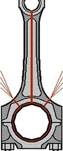
It is best to look at the liquid friction at a bearing of the crankshaft (picture above). So imagine the crankshaft on the inside and the two halves of the bearing shell or an enclosing connecting rod on the outside. Between
them the engine oil, here now divided into different layers. The outermost layer is stationary at a main bearing with the bearing shells and the complete engine housing, while the innermost layer rotates with the crankshaft.
The layers in between must compensate for these speed differences. The more there are, the smaller the differences between them. However, it's always a prerequisite that the crankshaft will float evenly by its movement.
Of course, this is only possible up to a certain thickness of the lubricating film and also requires a certain minimum speed.
| Dependencies |
| F | proportional | Dynamic viscosity μ |
| proportional | Bearng area A |
| proportional | Speed difference Δ v |
| not proportional | Lubricating film thickness Δ x |
This results in the formula:
| Δv |
| F = μ · A · |  |
| Δx |
The dynamic viscosity is the constant here, which plays a role in any proportionality. If, for example, the rotational speed at the wheel is proportional to the speed, it is still not possible to set 1/min equal to 1 km/h. A
constant can be determined in this way, for example, by determining all other values by trial and error and then changing the formula accordingly. This results in the formula:
| F · Δx |
| μ = |  |
| A · Δv |
So if we move the surface of the slide bearing into the plane, it would be located between two plates of 1 m2 each with the (theoretical) distance of 1 m. If then a force of 1 N is needed to pull the upper plate
with the speed of 1 m/s, the dynamic viscosity is
| N · m · s | | kg |
| μ = 1 |  | = 1 |  | = 1 | Pa · s |
| m2 · m | | m · s |
And since, of course, oil very rarely occurs between two such large plates with this enormous distance, the most common unit is one thousandth of a Pa·s, namely one mPa·s (spoken millipascal second).
In terms of fluids, we distinguish water as a Newtonian fluid and, for example, motor oil as a non-Newtonian one. In the case of water, the resistance that it offers to movement changes proportionally to the speed. By the
way, for water the viscosity at 20°C and normal pressure is almost exactly 1 mPa·s. Since it can change with engine oil with the parameters described above, it can be 100 to 600 times higher even at a constant
temperature of 20°C.
The oil pump, which is usually driven by the crankshaft, maintains the oil circuit and guarantees an oil pressure that is again dependent on the speed. If the line system branches out, then apply at each of the branching
points, the inflow and outflow must be the same size (Kirchhoff's node rule). This applies to both outflow and later inflowing pipes. Since these are rigid, no oil can be stored temporarily. So additional flow-resistances
can come up, just because a part of oil is branched off and/or is added again later.
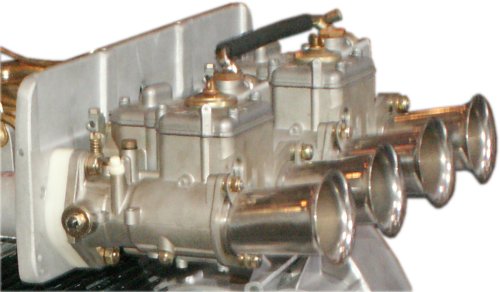
As with the cooling system, the flow resistance also depends on the other design of the circuit. Fits e.g. at the crankshaft play a role. The dynamic viscosity is also particularly important here. Another distinction is made
when looking at the flows of the individual layers. Famous in the car are the intake manifolds, in the past in sporty cars e.g. at the carburettors (picture below), today partly hidden in the air filter box.
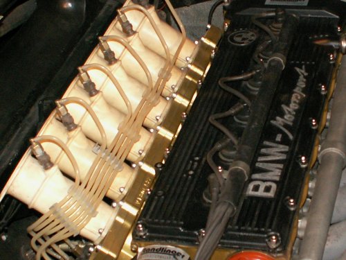
Below the system of a BMW M1 with open injection. The funnels are shaped in such a way that the air layer guided along the inside passes by without disturbances, which is called laminar flow. The funnels thus narrow
with decreasing angle. If vortex formation or turbulent flow occurs in any operating area, this has a negative effect, e.g. on the power output of the engine.
|