 Hydraulic brake - Two circuits Hydraulic brake - Two circuits
Much has not happened compared to the single-circuit brake. In principle, only the master cylinder has been replaced. The now has two pistons and each of them a primary and secondary cuff. However, one thing has
to be emphasized right from the start, the two brake circuits thus created are hydraulically completely independent of each other.
Clearly visible sign is the partition in the expansion tank, which allows a common filling, but at a certain level effectively prevents the outflow of the brake fluid of the one via the other brake circuit. You realize, the purpose
of the dual-circuit brake is to keep at least one foot brake circuit intact in the event of a defect.
And again, to repeat: you'll probably come across drawings while studying such a brake, that represent any components between the push rod piston right and the intermediate piston on the left, for example, springs or
a kind of small rod. Do me a favor, don't think that there is any mechanical connection between the two pistons that synchronizes the movement of the two. If the push rod piston is operated by the pedal, the force to the
intermediate piston is only transmitted by hydraulic. Only when returning to the starting position, there may be such a mechanism working.
In the case of mechanical connection, the independence of the two groups would be immediately jeopardized. Brake fluid under pressure must therefore be able to flow between the two pistons on the one hand and on
the left side of the intermediate piston into each of the brake circuits. Then goes back the push rod piston together with the pedal, it takes the intermediate piston in certain constructions with it to its initial position
(restraint).
So again: In the starting position, ie when the pedal is not pressed, the primary sleeves of the two pistons release the respective compensation port. Pistons that do not or never reach this starting position also do not
allow pressure equalization in the brake circuits operated by them. This inevitably leads to problems.
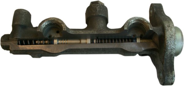
Incidentally, in earlier times you could remove the reservoir in such cases and then check the holes for the presence of a cuff out. In the picture above, that might still be possible, but since the master cylinders have
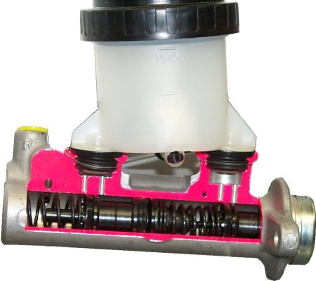
become more compact (picture below), the direct view from the top is often difficult.
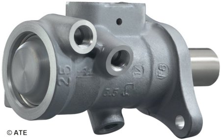
A more modern, much shorter form: plunger master cylinder
There are other reasons why the unhindered connection between the brake circuit and the container part is necessary. This can be in addition to the already mentioned wear and heating or cooling. Also, the respective
piston may have returned much faster from the braking as the springs could push the pistons of the wheel brake cylinders to their starting position.
It may therefore be that for a short time there is too much brake fluid in the compartment between the primary cuff and the wheel brakes, which must flow through the open inlet and outlet port back into the expansion
tank. So
you now know where both have their name from. Now it's time to get to the actual task of the tandem master cylinder.
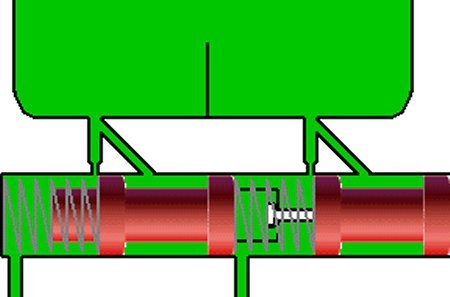
For the following is very important to note the starting position for the following figures. Both pistons are on the right side to stop. Their springs have the greatest possible decompression. The bondage between the two
pistons allows a reduction in the distance, plays only a role in the withdrawal of braking. Here it ensures the safe release of the left compensation bore.
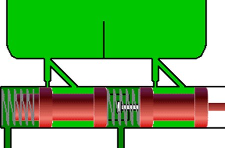
Now the brake was fully operated. Naturally, the push rod piston has to travel much more distance, because here the intermediate piston has to be added. Both springs are cocked, both brake circuits intact.
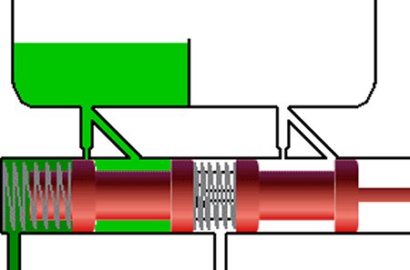
Now a leak in the right-going brake circuit is assumed. The driver has noticed that the pedal travel has increased considerably. After several pumping attempts to improve this situation, eventually all the brake fluid
escaped. Now both pistons are really mechanically connected and only the intermediate piston stabilizes a bit with its brake circuit.
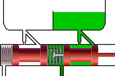
Now a leak in the left brake circuit is assumed. Again, all brake fluid has escaped and the pedal travel is very long. But even before reaching the bottom plate so much pressure is built up between the two pistons, that it
is enough for the right brake circuit. But if you think that the dual-circuit brake is sufficiently explained, we unfortunately have to disappoint you.
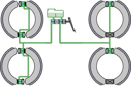
It is about the division of the two circles, because the above black and white division is unfortunately not ideal when it hits the front brake circuit. Incidentally, it is the most common and used in trucks exclusively these
days. But allow us to present the only remaining second possibility besides the abundance of possibilities.
It's complicated enough anyway, called 'diagonal split'. It connects each front left with rear right and front right with back left. Advantage: No matter which circuit fails, there is still half the braking effect available.
Disadvantage: The vehicle threatens to break out to the side, which is still intact on the front axle.
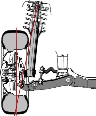
The problem is solved by countersteering. No, you can not expect that from the driver. It has to happen automatically. The construction at the picture below shows it, the negative steering wheel radius. The pivot axis of
the wheel hits the ground outside the center of the contact area of the tire. If at both wheels braked equally strong, you notice nothing of it. But if a wheel brakes more strongly, a moment is created on the ground, which
causes the wheel to steer to the other side.
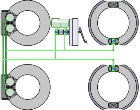
And if you do not believe that there are no more brake circuit partitions because they are mentioned in other books, then research or ask in workshops. For example, if one of the mechanics has ever seen two brake
lines leading to a normal wheel brake. That would be the prerequisite for the safest of the systems, which always summarizes the complete front axle and one rear wheel each in a brake circuit (picture below).
|