
|
Inertial forces and -torques
The advantage of internal combustion in the piston engine is coupled with the difficulties of having to convert the resulting to and fro (oscillating) movement into a rotation. If you compare this action with the elegance of
the rotary-piston engine, you'll know why it was once developed as an alternative. In contrast to the rotary engine, the running of the piston
engine must be made smoother by using more cylinders, counterbalances and balancer-shafts.
We're talking about inertia forces, which can be easily recognised by looking at the above connecting rod. This is made up of the upper part (small-end), together with the oscillating piston, gudgeon pin and piston rings,
and the lower part (big-end) which is bolted to the rotating crankshaft-pin. Basically, one could divide the con-rod into two parts, each part being assigned with the respective inertia. Perhaps it would be possible to
completely compensate for the centrifugal forces of both the oscillating- and the rotating part of the crank-drive by placing counterweights on the crankshaft.
Actually, this is not really a good idea, since they would only
function at the top dead centres. After all, with a crank angle of 90°, the counterweights have nothing to put up against the centrifugal force coming from the piston. Thus, they have to be content with about half
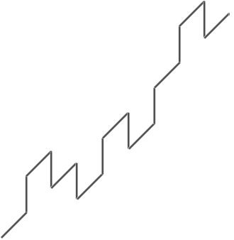
compensation. This again means, that between TDC and BDC the oscillating forces rise and fall. They are described as being second order inertia forces and are shown by the blue curve in the diagram below.
So, the inertia forces move the engine as a whole, upwards and downwards. First order forces occur in rhythm with the crankshaft, those of the second order, occur twice as often. Both types of force can be subdued by
using compensation shafts. In a single-cylinder engine however, both forces occur, which is why it needs two compensation shafts, each one running at the respective RPM of the occurring forces. In this case, it's
worthwhile considering to have more cylinders.
So, what then is inertia-torque? This is only found in multiple cylinder engines. Have a look at the well known crankshaft of a four-cylinder in-line engine. It's first order forces are balanced out. Indeed, because all the
crankpins are on one level, the result is second order forces between UDC and BDC.
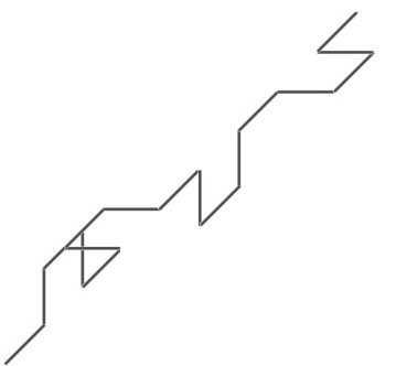
In this diagram of an unusual crankshaft, they would be perfectly balanced. However, where e.g., previously the front and the rear piston moved towards UDC or BDC at the same time, they now do at different times. The
result is: the engine see-saws around the transverse axis. The torsion in an axis having a certain strength is torque, which is why, in this case, one speaks of first- or second order inertia-torque, depending on the
frequency with which it occurs.
In-line three-cylinder engines also suffer, among other things as well, from this syndrome. How they can be compensated, can be seen in the video below towards the end. 06/14
| Engine | F1 | F2 | M
1 | M2 |
| In-line three-cylinder | no | no | yes | yes |
| In-line four-cylinder | no | yes | no | no |
| Boxer four-cylinder | no | no | no | yes |
| In-line five-cylinder | no | no | yes | yes |
| In line six-cylinder | no | no | no | no |
| Engine type | F1 | F2 | M1 | M2 |
| V six-cylinder | no | no | yes | yes |
| V eight-cylinder | no | no | yes | no |
| V twelve-ylinder | no | no | no | no |
F1/2Inertia-forces 1./2. order,
M1/2Inertia-torques 1./2. order
|
|