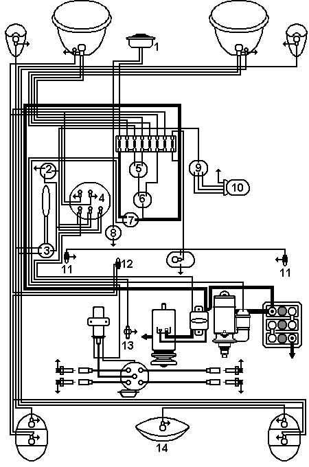
Electrical system

| Nr. | Part | Nr. | Part |
| 1 | Honk | 8 | Honk operation |
| 2 | Indicator relay | 9 | Wiper switch |
| 3 | Indicator switch | 10 | Wiper motor |
| 4 | Speedometer-control switch | 11 | Ignition switch |
| 5 | Main beam-/full beam-foot switch | 12 | Brake light switch |
| 6 | Main beam switch | 13 | Oil pressure switch |
| 7 | Ignition start switch | 14 | Number plate light |
At the end yet (similar to the original) schematic diagram of the 1200 A (model 1964). Of course, even with 6-volt system, direct current-generator and 8 safety fuses, in addition to the 6 for thelighting system one for battery positive (30) and ignition (15). The circuit diagram fits easily on a DIN A4 page.
Earlier page
Beetle engine 3
Next page
Maintenance schedule
cartecc.com
Top of page
Index
2001-2015 Copyright programs, texts, animations, pictures: H. Huppertz - E-Mail
Translator: Don Leslie - Email: lesdon@t-online.de