Steering trapeze 1 Steering trapeze 1
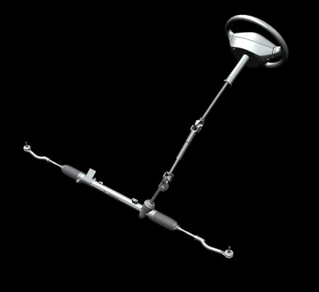
To better understanding, please follow a longer thought experiment. Get up (in mind) and stretch out your arms. Clench your hands to fists. Now so called kingpins are put into your fists, each a piece of round
steel, far protruding on both sides. Turn with your fists, the kingpin into the vertical.
Thus, we have recreated the main part of the classical front axle quite well. It is called stub axle even today, for example, in the truck segment. Now being added metal brackets, which enclose your fists one-
sided. This results above and below your fists to each a bearing that interconnect the brackets.
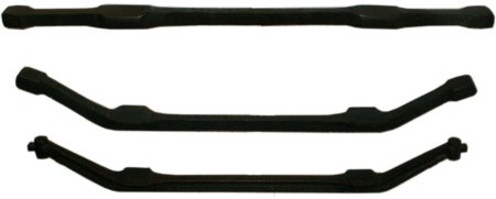
It should be emphasized once again that one denotes the two bolts, you still have in your fists, as steering knuckles and the steering accordingly as 'axle-pivot steering'. By the way, one has to consider, what
part should be pivoted on the steering knuckle and which part should hold very firm by a so-called press fit the steering knuckle.
We choose the by far most common method, by providing the brackets with bronze bushings and therewith make this rotatable on the in the stub axle firmly clamped steering knuckles. Of course, this is not so
simple, because such a bushing must be designed in diameter this way, that there is only a little clearance between it and the steering knuckle. If we would place the press fit into the bracket and the bronze
bushing in the fist, that would be much more unfavorable for the strain and durability.
The clearance shows oneself by touching the jacked up wheel top and bottom, and then tries to move. This is of course easily possible only when a passenger car, but has the disadvantage that today's cars
have no more kingpins. Nevertheless, of course, such an examination is useful. Although modern trucks have still kingpins, but no more bronze bushings, but needle bearings for easier steering.
By the way, the antonym to the stub axle is the fork axle. Even today it still exists, and indeed in all-wheel trucks. Through its front rigid axle runs the also rigid drive shaft to the front wheels. Here, a continuous
kingpin would interfere. Therefore, it is divided into an upper and a lower part and so let through the drive shaft. By the way, the needs exactly a joint in the intersection with the two axes of the steering knuckles.
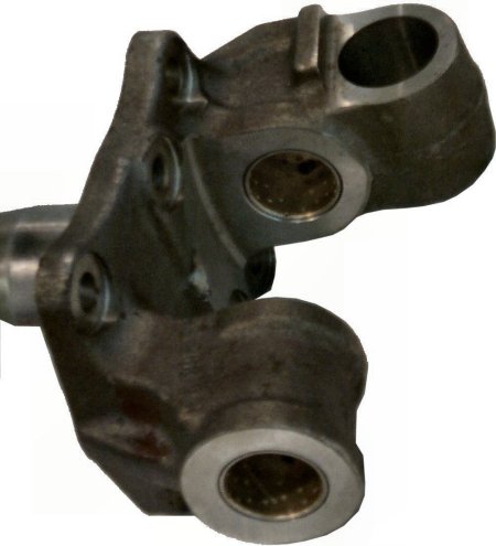
Here once again, a separate steering knuckle with bushings for plain bearing. Case of modern trucks prevails at these locations rolling bearing. To repeat: In a steering knuckle axle each steered wheel has its
own rotary axis or better swivel axis, in contrast to the drawbar axle known from the horse-drawn carriage.
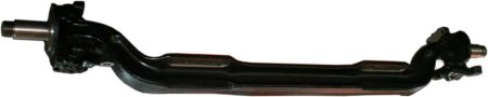
We extend the brackets notionally, while we set again steel bolts, but this time approximately in the center of each bracket and respectively facing outwards. Whether the two bolts are welded on or casted
together with the brackets, we ignore here. It is important that on these bolts in addition to the brake discs/drums, the wheels run, which are steerable by the rotatability of the brackets.
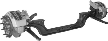
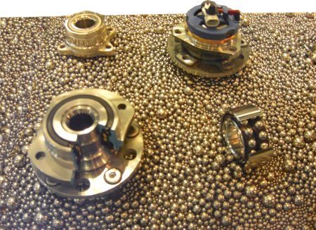
The two horizontal bolts, on which the wheels are running, are the so called 'wheel hubs'. The wheels also do not run directly on them, but we have still roller or ball bearings, so in any case, rolling bearings
there between, called in this case, 'wheel bearings'.
It's a disadvantage that the steerable wheels are still not connected to the steering wheel. Therefore, must be mounted levers from the same material on the two brackets left and right. They are relatively slender
and often slightly curved, because they both extend backwards around the tire, sporadically forward, too. They are called 'steering levers'.
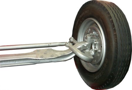
Imagine at their ends eyelets, in the e.g. screws could be inserted from above. If one would connect the two by the so-called tie rod, then something like steering would be possible by to-and-fro movement of this
rod. However, a prerequisite would be at least simple joints instead of bolts between tie rod and steering levers.
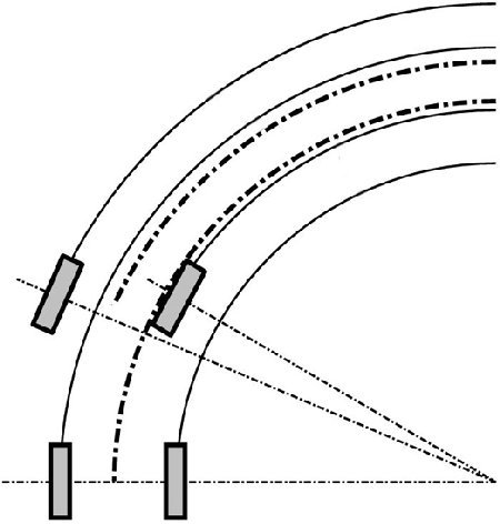
However, if you now assume that the two wheels remain exactly parallel when turning, you are regrettably mistaken. Because as you possibly can recognize top on the picture of a front vehicle, the inner curve
wheel has the smaller turning radius and must therefore be more deflected.
Here, the confirmation again. Only when two wheels roll on the same radius, they can be aligned parallel to each other. This is basically the case with the rear wheels, because the midpoint of a two-axle vehicle
when cornering always is on the extension of the rear axle (see figure below). But the front wheels have different radii and therefore different steering angles.
Land vehicles are generally steered via the front axle. That is, for example, case of forklifts differently because of their incredibly important mobility in tight spaces. But quickly you could drive on the road with a
steering only on the rear axle not without risk of accidents.
The reason is that the rear axle should to be headed to the outer edge of the curve, in order to be able to pass through. This evasion outward would be for their cornering force a big advantage and at the same
time for the front axle a disadvantage. The driving behavior would be almost even worse than that of a tricycle with up front only one wheel.
Now, we still unconsciously fiddling with at least two new terms. The first is the track. The can be defined as difference measure between the wheels of an axle front or rear. Then it would be indicated in
millimeters. That would not be exactly because unclear where at the wheels could be measured. Usually one would take the rim flange, the part of the rim the farthest from the center.
Of course, an angle would be more favorable whereby whole degree numbers are not sufficient. So, one falls back to the division of one angle degrees into 60 angle minutes. But in the workshop, one first brings
the steering in a clearly defined straight-ahead position and then measured in relation to the longitudinal direction of the vehicle. Then results for each wheel, a single value for the track.
The value can be positive for 'toe-in' and negative for 'toe-out'. In the first case the respective wheel steers too much inwards, in the second too much outward. But that means in no way that the track of each
wheel is always set to zero. Previously, the manufacturers selected on the front axle with front-wheel toe-out and with rear-wheel drive toe-in. The idea was that pushed wheels overcome by clearance in the
steering linkage toe-in and pulled the toe-out.
Here we are at a further problem of the chassis. Nothing can be fixed to a tenth or hundredth of a millimeter. Already our so far very simplified construction contains points that cannot be completely free of
clearance, for example, the connection of the tie rod to the steering levers or the wheel bearings. But this is harmless, because today is almost every series in contrast to the race-chassis mounted completely
in rubber.
And of course, the tire contact to the roadway is from almost pure rubber, at least not verifiable with absolutely fixed values. This is also a part of the reasons why the wheels do not run with total track zero.
Their track deviates slightly from zero, which, for example, clearance finishes by slightly horizontal wheel forces and eliminates the tendency to flutter around this clearance. But that's not the only reason for a
track unequal zero.
And because we have turned in the wheels already and the indeed are not parallel to each other, there is the second important term, the 'relative steering angle'. After all, its name already indicates how it is to
determine, namely, between the wheels of an axle. Now, the steering angle must be determined still, where the relative steering angle is measured, usually at 20° of the wheel inside of the curve.
However, here too the producers deviate from the principle of best possible run of the wheels through the curve. This can be heard even if, for example, a vehicle is pushed from one to the other place on the
stone or plastic floor of the car showroom and thereby steered vigorously. Thereby, the front axle or their tires virtually scream out that they do not roll off free of lateral force.
In the construction one gives the front axle the values in such a way, in order e.g. to turn the outer wheel a little stronger. This can have, for example, a positive effect on the maneuverability in curves. Anyway,
the inside wheel is less involved in the guidance of the vehicle, because it lacks simply the pressure on the roadway. The faster you drive around the curve, the more it will be relieved.
Please do not ask here for a further justification, because the can be manifold. A chassis is developed not only on the drawing board, if at all something will created still on this. It is the result of long experience
and many driving tests. No matter how many great chassis parts you buy together. The result is by no means guaranteed when the combination was not tested by professionals at this vehicle.
The question is not yet answered, how this effect is ever achieved that the outer curve wheel stronger turns. For this purpose, we must look again more precisely on the two steering levers. First, it is to define,
they go backward and not forward. So, the tie rod is arranged behind the front axle.
But, they are not only sometimes bent artfully in order to come past the tire or to have no contact with it, but also a little oblique. This means the center distance of the two joints is smaller at the tie rod than the
center distance of the two kingpins. One calls the square formed from the axle body, tie rod and steering arm also 'steering trapeze'.
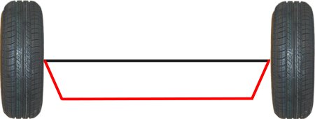
Previously, you were perhaps thinking that one could move the tie rod below on a straight line to the left or right. But that's not true, as you can see in the picture below. Since this is a steering trapeze, the
parallelism of the two longer sides is repealed above and below.
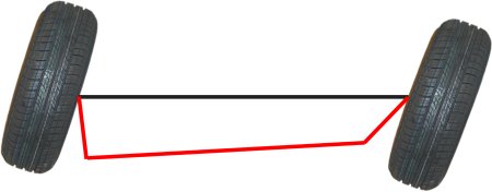
But much more important are the two shorter sides. The greater the difference in length of both sides above and below, the more the angle of the two sides left and right move away of each other and thus
generate different steerable wheels. Of course, all this must be matched on the geometric dimensions of a particular vehicle.

|