 Transformer Transformer
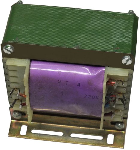
Used a thousand times, but how does it actually work, the transformer? We don't just want to investigate how a transformer converts AC voltage of a certain size into DC voltage of a different order of magnitude, but also
whether the same technology can only be used to change DC voltage.
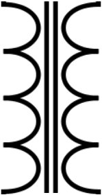
You will know the basic principle. Although the coils are distributed differently in the picture above, we now want to assume the primary coil on the left and the secondary coil on the right. As usual with a circuit diagram,
assumed the same number of turns in each case. Of course, that wouldn't make sense in practice, because we at least want to change the voltage.
On the other hand, the circuit diagram cannot show every turns ratio because it can be quite large. At 230 V after 12 V that would be almost 20: 1. The question that remains is which voltage source is necessary here to
operate a DC motor.
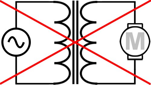
As you can see, this combination cannot work like this, because the AC voltage source generates something that the DC voltage motor cannot do anything with. And the transformer doesn't change anything about it.
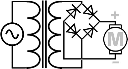
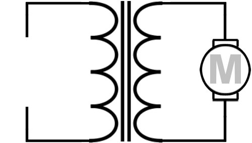
It's much better that way. Here the alternating voltage behind the transformer is converted into a direct voltage. There is a clear positive/negative polarity, so that the direction of rotation of the motor is also determined.
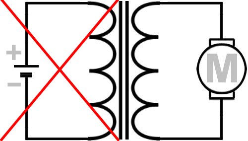
There must be another way. Why can't we use a direct current source directly? It looks nice, but it doesn't work. Because the transformer works on the basis of generating a constantly changing magnetic induction on the
primary side. In the picture above it does not change, it even harbors the risk of the primary side being destroyed by a short circuit.
The two coils in the transformer are basically nothing more than coiled wire. As a result, the magnetic field, already developing around every wire through which current flows, is significantly strengthened on the primary side.
As already mentioned, the gain then depends on the number of windings.
Conversely, a magnetic field building up around a conductor generates a voltage in it. Again, this depends on the number of windings. If the polarity is maintained with constant voltage, charges are formed, e.g. electrons
gather at the positive pole. But only the change in the magnetic field causes the electrons to flow. The movement of the electrons is also known as the electromotive force.
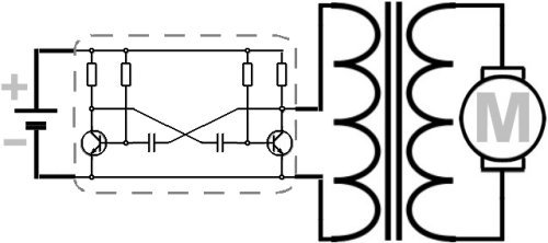
So far, however, we have assumed that the polarity of the magnetic field and thus also of the secondary side will interchange. However, there would also originate an electromotive force if the voltage only would change
between zero and a certain amount. This is exactly what the flip-flop in the picture below does. More on that later.
|