
|
 ALB regulator ALB regulator
| Automatic load-dependent brake force regulator with linkage on the chassis |
kfz-tech.de/PDB4
| Rear axle load in kg | Front brake pressure in bar | Rear brake pressure in bar |
Pressure air suspension in bar |
| 2000 | 5,2 | 1,4 | 0,5 |
| 3000 | 5,4 | 2,3 | 1,1 |
| 4000 | 5,6 | 1,7 | 1,7 |
| 5000 | 5,8 | 4,3 | 2,2 |
| 6000 | 6,0 | 5,4 | 2,8 |
| 7000 | 6,2 | 6,3 | 3,3 |
| 11500 | 6,2 | 6,7 | 5,5 |
| 12300 | 6,2 | 6,7 | 6,0 |
A truck differs from a car not only because it can transport large loads. The difference in weight between a full and empty vehicle is also significantly greater. If you ignore the tipping device and other special attachments on a
truck, the maximum payload can be about as large as the empty weight. While the payload on a trailer can be twice as large, on a car it can be at most half. This requires special precautions in the braking system.
If the rear axle were to be actuated with the same pressure as the front axle during partial braking even when the vehicle was unloaded, the rear wheels could lock and the vehicle could swerve uncontrollably. The load-
dependent brake force control ensures that the pressure is reduced depending on the load level. Conversely, the pressure on the front axle can exceed that on the rear axle under certain load levels.
The table above shows the brake pressures of the front and rear axles depending on the rear axle load. In addition, the pressures increasing in proportion to the rear axle load are output to the rear air bellows. When
checking the brake system, there is always enough pressure in the system when the engine is running or when it is filled with external air. Pressure gauges are connected to the respective service brake circuits at the front
and rear axles. Long hoses enable readings to be taken in the driver's cab when the brake is applied.
The second column of numbers from the left indicates the pressures that must be achieved by deliberately pressing the brake pedal on the front axle. The third column shows the pressures that must be achieved on the rear
axle. The tolerance can be cautiously specified as ± 0.2 bar, although any manufacturer specifications to the contrary must of course be observed.
This is therefore a targeted check of the automatic load-dependent brake pressure regulator (ALB). If there is leaf springs instead of air springs, the last column should actually contain the spring deflection in millimeters.
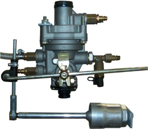
The picture above shows the linkage pointing downwards to the axle. The sleeve with spring at the bottom right enables the rod at the top directly on the regulator to be turned in both directions using simple tools, such as
cable ties.
The pivot point of the rod shows the amount by which it is twisted, thus simulating a larger load. This rod is carefully checked in terms of its length from the pivot point before each check of the brake pressure assignment.
The position in the unloaded state can be set using the rubber grommet on the left. The further relationship between front and rear axle pressure at different load levels can then be determined.
kfz-tech.de/YDB15
|
|